Fiber optics apparatus and method for accurate current sensing
Abstract
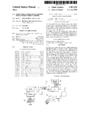
The fiber optics sensor includes a polarization maintaining optic fiber forming an optical loop, and a sensing medium coupled to the optic fiber and disposed generally midway in the optical loop. First and second quarter waveplates, coupled to the optic fiber and oriented at approximately 45° with one another in close proximity to the sensing medium, convert two counter-propagating linearly polarized light waves traveling in the optical loop into two counter-propagating circularly polarized light waves prior to passing through the sensing medium. The first and second quarter waveplates further convert the counter-propagating circularly polarized light waves into two linearly polarized light waves after exiting the sensing medium. The counter-propagating circularly polarized light waves passing through the sensing medium experience a differential phase shift caused by a magnetic field or current flowing in a conductor proximate to the sensing medium. A detector is coupled to the optic fiber and detects the differential phase shift and produces an output in response thereto.
Collections
Citation
(1999). Fiber optics apparatus and method for accurate current sensing. United States. Patent and Trademark Office; Texas A&M University. Libraries. Available electronically from https : / /hdl .handle .net /1969 .1 /176624.